
Проверка соединения и сетевых настроек
Проверка соединения
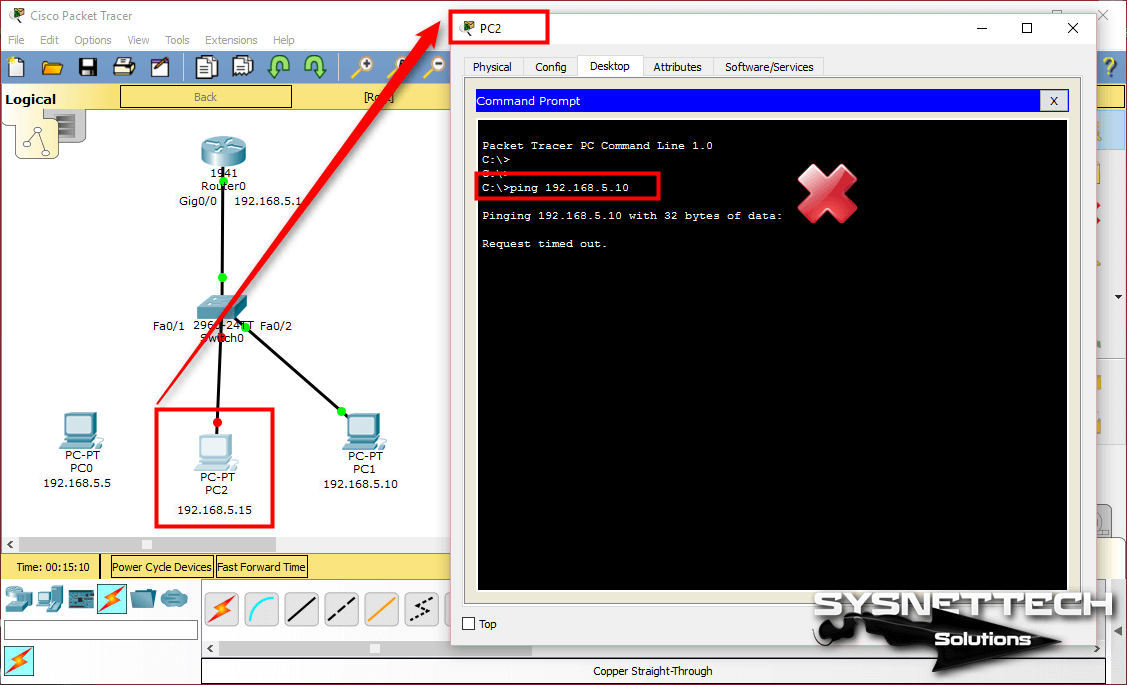
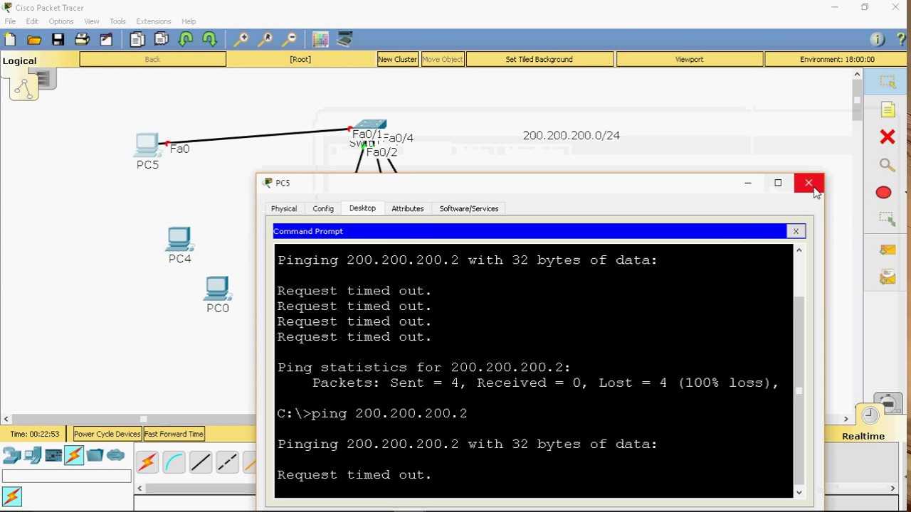
Перед началом работы с роутером 1941 необходимо убедиться в его корректном подключении к сети. Для этого можно использовать команду ping, проверяющую доступность других устройств в сети:
- Выполните команду ping в командной строке роутера.
- Если ответ получен успешно, это означает, что соединение корректно настроено.
- Если ответ не получен, проверьте параметры подключения, настройки сетевых устройств и возможную блокировку доступа сетевыми настройками в брандмауэре.
Настройка сетевых параметров
Для корректной работы роутера 1941 необходимо правильно настроить сетевые параметры, такие как IP-адрес и маску подсети:
- Выполните команду enable в командной строке роутера для входа в режим настройки.
- Выполните команду configure terminal для перехода в режим настройки интерфейсов.
- Выполните команду interface , чтобы выбрать интерфейс, который будет настроен.
- Выполните команду ip address , чтобы задать IP-адрес и маску подсети интерфейса.
- Выполните команду no shutdown, чтобы включить интерфейс.
- Выполните команду exit, чтобы выйти из режима настройки интерфейсов.
- Сохраните настройки с помощью команды write memory и перезагрузите роутер.
После настройки сетевых параметров необходимо повторно выполнить тестирование соединения, чтобы убедиться в корректной работе сетевых настроек роутера.
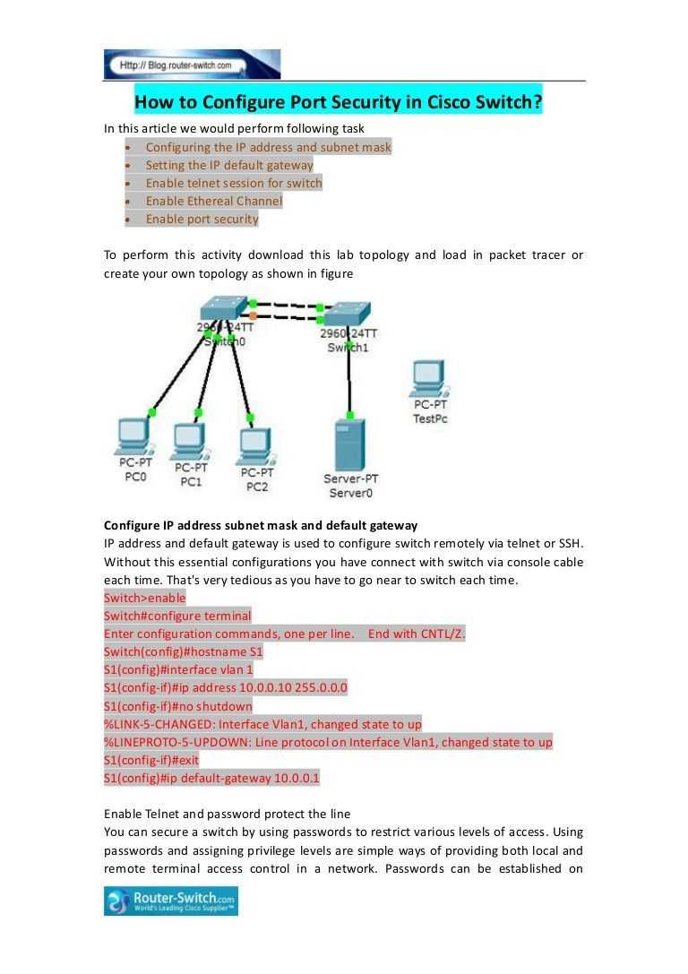
How to create read-only user accounts on a Cisco router using Packet Tracer
In this post, I will share with us on how to create read-only user accounts on a Cisco router. If you lead a team of network administrators, among them, those you want to only read configuration commands but not change anything, or you simply want to allow someone else access your router and help troubleshoot an issue without making configuration changes, then you need to create a read-only account for such a user. The read-only account will allow a user log in and read configurations without being able to make changes.
I will create a read-only account on a cisco router and apply it to the vty line. This will allow users access the router via ssh and read running configuration commands. Any attempt to issue commands other than the ones allowed for such users will be refused and an invalid message will be displayed.
To accomplish this task, I will create two accounts; the administrator account with full access and the read-only account. I will then configure ssh and instruct the router to authorize vty logins with the local database. This task will be done using the Cisco Packet Tracer. The configuration is the same for live Cisco routers.
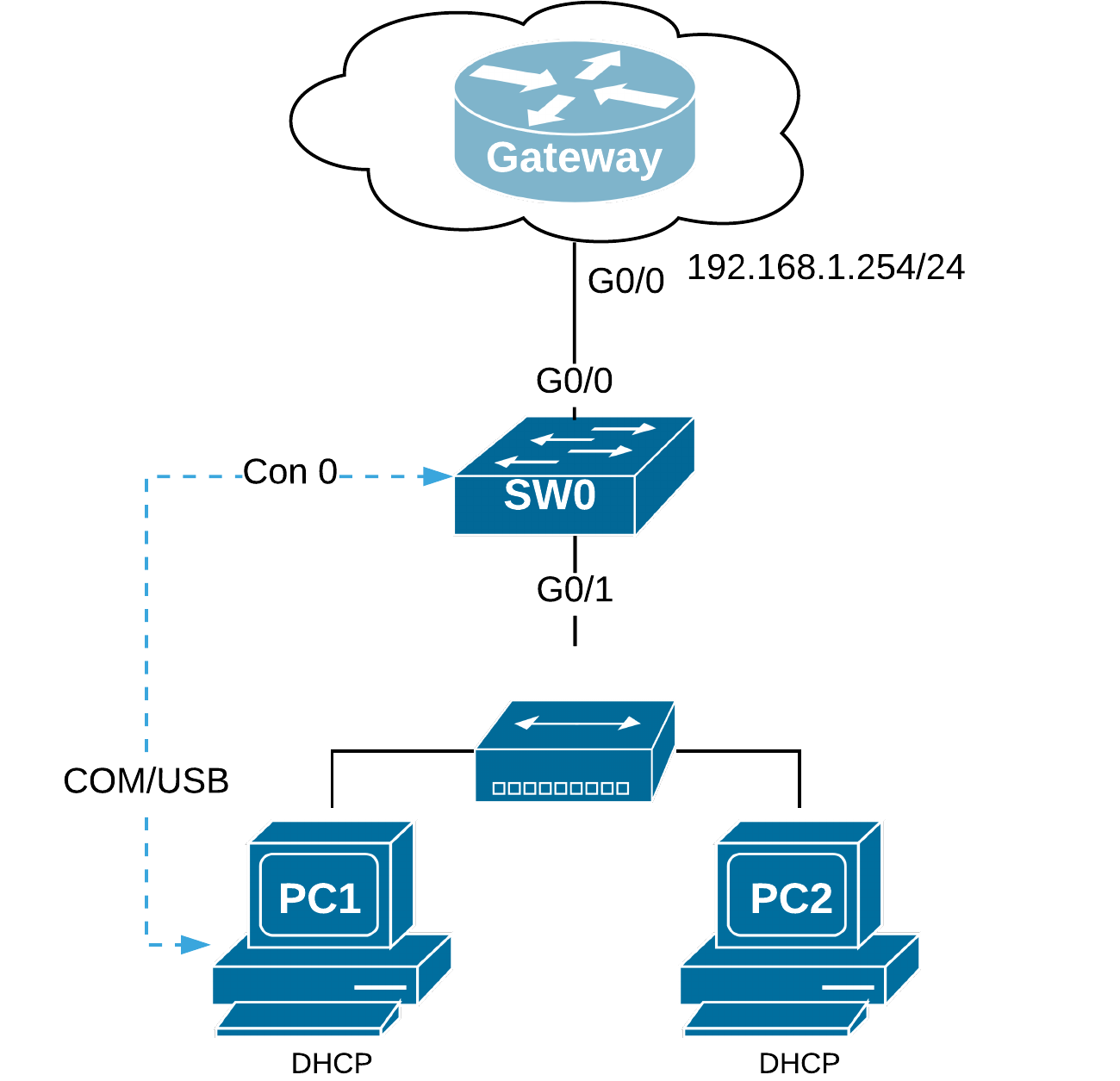
Network Topology
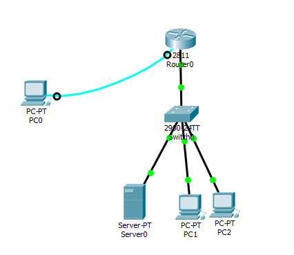
Create users in the local database
Router(config)#username superadmin privilege 15 pass cisco
Router(config)#username test privilege 3 pass cisco
You must have an administrator account with full access, then the read-only account. Level 15 is the highest while level 1 is the least. Next, we specify the privilege level available to the user.
Router(config)##privilege exec level 3 show running-config
Now, let us configure ssh and instruct the router to authorize ssh users using the local database
Timigate(config)#ip domain-name yourdomain.com
Timigate(config)#crypto key generate rsa
Enter a value for rsa key. I used 1024
Timigate(config)#ip ssh authentication-retries 3
Timigate(config)#ip ssh time-out 3
Timigate(config)#line vty 0 4
Timigate(config-line)#transport input ssh
Verification
To verify, I will log into the router via ssh using the read-only account and then try to go to the global configuration mode. See below.
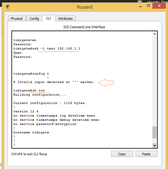
You can see that an attempt to go to global config mode was refused and an “invalid input detected at ‘^’ marker.” message was displayed. But right after that, the ‘sh run’ command was issued and the running configuration on the router was shown.
Типы списков ACL для IP
В данном разделе документа описываются типы списков ACL.
Стандартные списки ACL
Стандартные списки ACL — это самый старый тип ACL. Их появление датируется выпуском ПО Cisco IOS Release 8.3. Стандартные списки ACL управляют трафиком, сравнивая адрес источника IP-пакетов с адресами, заданными в списке.
Ниже приведен формат синтаксиса команд стандартного списка ACL.
Во всех версиях программного обеспечения номер access-list-number может варьироваться от 1 до 99. В ПО Cisco IOS Release 12.0.1 стандартные списки ACL начали использовать дополнительные номера (от 1300 до 1999). Эти дополнительные номера относятся к расширенным спискам ACL для IP. Программное обеспечение Cisco IOS Release 11.2 предоставило возможность использовать имя списка (поле name) в стандартных ACL.
Параметр source/source-wildcard, равный 0.0.0.0/255.255.255.255, можно указать как any. В случае, когда используются только нули, шаблон можно опустить. Поэтому сервер 10.1.1.2 0.0.0.0 аналогичен серверу 10.1.1.2.
После определения списка ACL его нужно применить к интерфейсу (входящему или исходящему). В более ранних версиях программного обеспечения «out» (выход) было значением по умолчанию, если не было задано ключевое слово «out» или «in» (вход). В более поздних версиях программного обеспечения необходимо указывать направление.
Ниже приведен пример использования стандартного списка ACL для блокирования всего трафика за исключением трафика из источника 10.1.1.x.
Расширенные списки ACL
Расширенные списки ACL появились в ПО Cisco IOS Release 8.3. Расширенные списки ACL управляют трафиком, сравнивая адреса источника и места назначения IP-пакетов с адресами, заданными в списке.
Ниже приведен формат синтаксиса команд расширенных списков ACL. Некоторые строки были обрезаны из соображений размещения.
Если вы считаете, что её стоило бы доработать как можно быстрее, пожалуйста, скажите об этом.
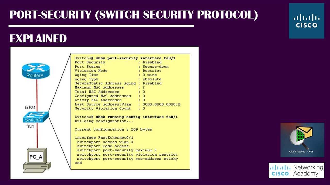
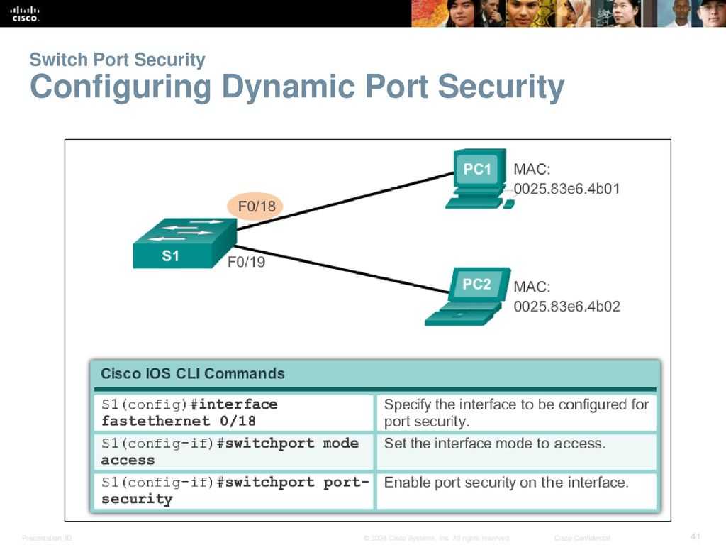
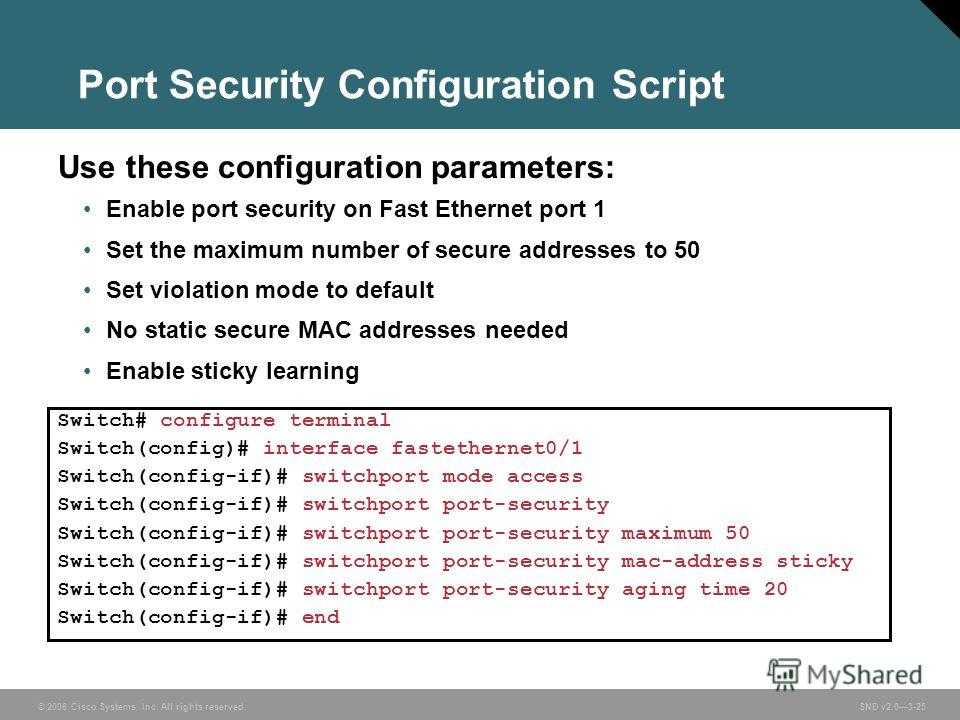
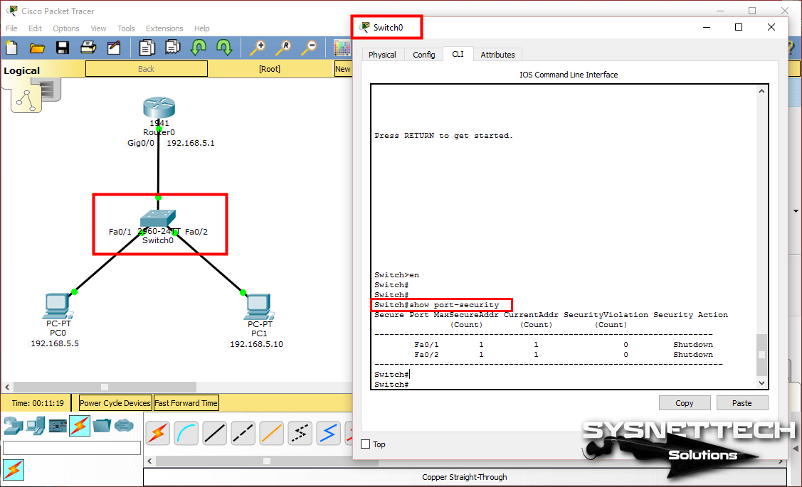
Step 4: Configure Switch interfaces
Check all the interfaces that will be used and shutdown any that will not and assign them to the black hole vlan.
Then configure the switchport assignment for the end hosts(f0/1-7).
I recommend selecting the whole range and applying all of the commands except the switcport access vlan. Then select a smaller range per clan and apply that command to prevent error.
Then select smaller range per vlan on topology and enter:
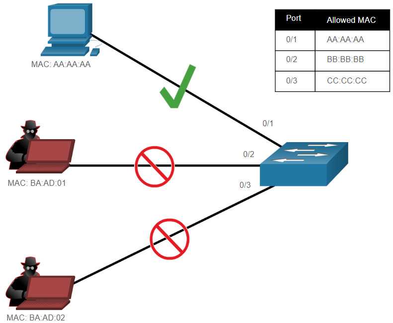
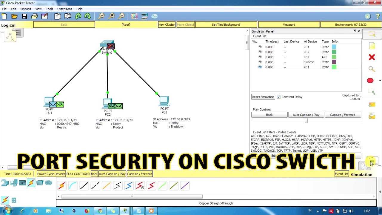
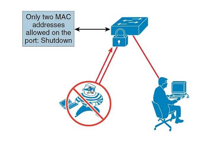
The two port-security commands set the port to only have a single mac-address assigned automatically when activated in the interface…if this is violated the port will automatically shutdown until reset by the administrator (shutdown then a no shutdown will do).
So for example say you had a voip phone daisy-chained into the end host would have to set allowed mac-address to two by using the command switchport port-security maximum 2 or the port would be shut down
Also once the lab is done the end hosts need to be unplugged and replugged back into interfaces so the switch can dynamically learn the mac address or a shutdown followed by a no shutdown on each switchport interface.
Next, the only interface left to configure () going to the router needs to be configured as a trunk.
Step: 7 Finally its time to finish up with static routing
If you’re using packet tracer it does not allow you to shutdown the process so you should enter the routes default with a lower administrative distance. After testing you will remove them with no command and replace with the same routes with higher administrative distance than .
So … is the command needed to remove dynamic routing so static routing can be configured… do this on both routers
R1
static route syntax:
Then on Outer
The list of static routes above cover connection to the three different user lans and a route out to the interet. The order of the routes has a huge effect in the same way as access lists.
Static routes are chosen by administrative distance which is the last number in the command (If not specified like the first entry it assumes the default which is 1).
So based on the list the first the user vlans take priority and any other traffic is caught by the default static route which matches any network on the internet. If I put the default route first this would have caused major issues. There can be only one default route that should be set out towards the internet to ensure connectivity so it will hinder the ability to route traffic from my internal LANs from my private network.
Now if you internet gateway through any of PCs 1-6 you have connectivity without any dynamic routing.
Static routes have an AD of 1 by default, EIGRP is an AD of 90. By default static route will have priority over EIGRP due to their lower AD unless set otherwise.
This is not necessary in this lab but helpful in a situation where static and dynamic routing is set up as primary/backup.
Example:
Как создать пользователя в cisco packet tracer
В этой статье мы рассмотрим простое добавление нового пользователя на коммутатор Cisco, хранение пароля в зашифрованном виде, а так же указание прав для уровня привилегий и назначение точных прав для нового пользователя.
По умолчанию командный интерфейс CISCO имеет два уровня доступа:
- User EXEC mode – (1) первый уровень. Доступ к небольшой информации о состоянии устройства, т.е. только чтение и то не всего.
- Privileged EXEC mode – (15) пятнадцатый уровень. Полные права на все команды устройства, правка и чтение.
Так им образом, выставляя права от 0 до 15 уровня, можно сконфигурировать права на выполнение определённых команд для пользователя.
Итак добавим пользователя для чтения информации о коммутаторе (только просмотр)
Теперь добавим пользователя с полными правами
- Первая строка «configure terminal» — зашли в режим правки конфигурации
- Вторая строка «username admuser privilege 15 secret TestPass$$» — добавили пользователя «admuser» — имя пользователя «privilege 15» — права для него «secret TestPass$$» — пароль пользователя
- «exit» — выход
- «write » — записали в конфиг
Если мы хотим хранить пароль на коммутаторе в зашифрованном виде, т.е. что бы когда второй администратор читает конфигурацию он не видел вашего пароля.
Итак уточним синтаксис «username» :
Step 6: Finally its time to do some routing and get some traffic out
First do on then .
Getting into routing it is import to understand the general concepts of routing updates and administrative distance (described below).
Administrative distance is an honor system for a router to establish which routes are most trustworthy… it is an extremely important concept to understand for being able to truly understand routing.
Remember do which is the command used for determining the locally connected networks that need to be routed and makes the task incredibly simple.
R1
Passive-interfaces suppress routing updates which are not needed for your LAN networks or external interface to internet. The fact that they provide routing information can make them a security risk while producing extra traffic that provides no value.
in global non configuration mode type to see optionswith viewing your eigrp configurationssh
Troubleshooting Access Lists
To troubleshoot Access Lists at the CCNA level, we can use a single – yet powerful command. We are talking about the , or commands, that are essentially the same. The output shows the list of rules, excluding remarks, as well as the hit count. Note that the implicit deny is not shown here, and this is why we needed to add an explicit one. Here’s the output with the lab finished.
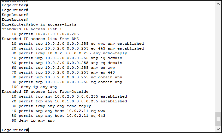 Here we can see all our access lists.
Okay, but we can see the same information from the running configuration, or even more considering remarks. What’s the benefit of this command? It shows the hit count. With it, you can see how many times an ACL matched until now. To verify that, try to navigate using the PCs in your lab: go to , or from internal PCs, and to from the outside client. Then, log back into the router and type the command again.
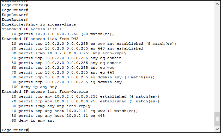 Now we can see how many time each rule matched.
And this is it! With that, you can know which rule is matching and whether you need to modify it or not. Try to do a few tests by pinging from the outside, and see the count grow on the deny rule.
Modify a single rule inside an ACL
It can happen that you just mistype a rule inside an ACL. However, we haven’t covered the method for replacing a single rule. Deleting and re-creating an entire ACL is simple, you just need to put a “no” in front of . But editing rules inside an ACL can be tricky.
First, you need to enter the Named ACL Prompt configuration. No matter what type of ACL is, edit it with the . Then, using , identify the IP of the rule you want to delete/edit. And then just type no, followed by the ID. If you want to delete the rule 50, for example, you can type . Then, to insert a new rule in place of it, type the ID followed by the rule. For example, .
Initial Setup
1/ Use a crossover cable to connect the routers together. We are using the 1941 Routers for this topology.
2/ Connect the other devices together using a straight through cable connection.
3/ Perform initial router configuration.
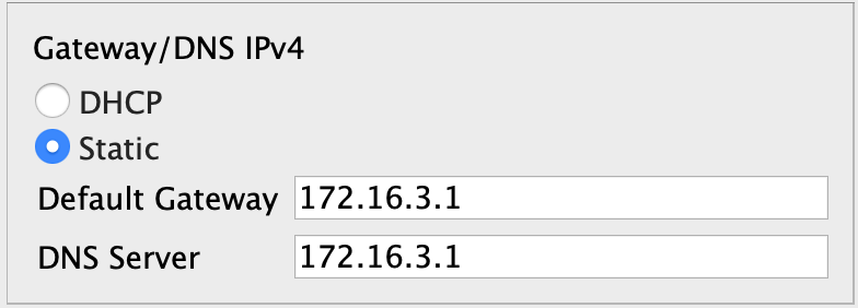
Configure the interface IP addresses on the routers and a default route on R_01 and R_03 pointing to the R_02 router. The R_02 router acts as an internet provider and has no knowledge of other networks except its directly connected network.
    hostname R_01
    interface g0/1
    ip address 172.16.1.1 255.255.255.0
    no shut
    interface g0/0
    ip address 100.100.100.1 255.255.255.0
    no shut
    exit
    ip route 0.0.0.0 0.0.0.0 100.100.100.2

    hostname R_02
    interface g0/1
    ip address 100.100.200.2 255.255.255.0
    no shut
    interface g0/0
    ip address 100.100.100.2 255.255.255.0
    no shut
    exit

    hostname R_03
    interface g0/1
    ip address 172.16.3.1 255.255.255.0
    no shut
    interface g0/0
    ip address 100.100.200.1 255.255.255.0
    no shut
    exit
    ip route 0.0.0.0 0.0.0.0 100.100.200.2
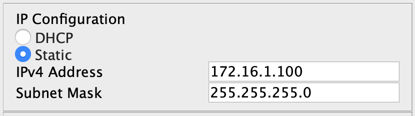
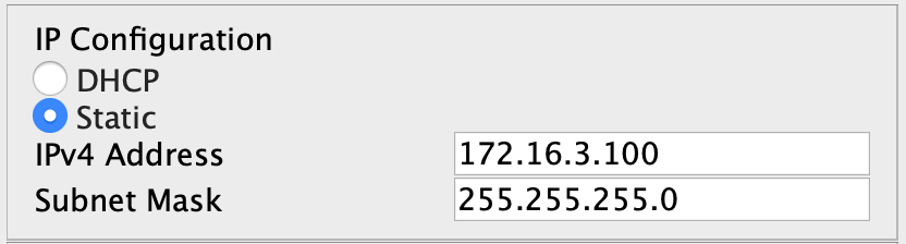
4/ Ensure that the laptops have static IP addresses configured. Laptop0 should have IP 172.16.1.100/24. Laptop1 should have 172.16.3.100/24. Attempt pinging across from Laptop0 to Laptop1. This should fail as R_02 does not know how to route this traffic.

    !Laptop0
    ping 172.16.3.100

    !Laptop1
    ping 172.16.1.100
5/ Activate licensing on the edge routers. Ensure that you have the security license enabled on R_01 and R_03.
    show version
    license boot module c1900 technology-package securityk9
    copy run start
    reload
    show version
Basic commands for all devices
| enable | <– Enters global mode which is used to access configuration terminal mode |
| conf t | <– Enters configuration terminal mode |
| hostname | <– Sets the devices hostname |
| hostname privilege 15 secret | <– Sets the devices username and password (using physical hardware gives more options of encryption algorithm type |
| no ip domain-lookup | <– Prevents device from preforming dns lookups (leave that to a network server) |
| ip domain-name | <– Assigns the domain name that the device is associated with |
| enable secret | <– Assigns MD5 encrypted secret as the password for entering enable mode |
| service password-encryption | <– Encrypts stored passwords |
| secure boot-image | <– Runs integrity check on system image(Router Only) |
| secure boot-config | <– Runs integrity check on startup-configuration(Router Only) |
| banner motd $ Unauthorized Access Is Strictly Prohibited. $ | <– Message of the day banner |
| banner login $ Unauthorized Access Is Strictly Prohibited. $ | <– Login banner(Router Only) |
| no cdp run | <– Disables Cisco Discovery Protocol |
| ip cef | <– enables Cisco Express Forwading(Router Only) |
| line con 0 | <– Enters console line |
| login local | <– Sets login to locally set users |
| logging synch | <– synchronizes the console to prevent interruptions from logs |
| exec-timeout 5 0 | <– Creates a timeout of 5 minutes of inactivity |
| session-limit 1 | <– Limits to a single console session for the device(Router Only) |
| privilege level 15 | <– User logging in need a username with a 15 privilege level assigned |
| transport output ssh | <– Allows the user to only SSH out of the device (NEVER use telnet, Router Only) |
| line vty 0 4 (its line vty 0 15 for switches) | <– Enters Virtual Terminal Lines |
| login local | |
| exec-timeout 5 0 | |
| session-limit 1 | |
| privilege level 15 | |
| transport input ssh | <– Allows only SSH into the device |
| transport output ssh |
| line aux 0 (only on routers) | <– Enters auxillary line |
| login local | |
| exec-timeout 0 1 | <– Creates a timeout of 1 second so even if the password is cracked the threat actor will be logged back out |
| session-limit 1 | |
| privilege level 15 | |
| transport output none | |
| end | |
| wr | <– Write the running configuration |
Type in global mode to see what has been done so far. This can be done in other configuration tiers with show commands with…
This is very helpful with confirming the configurations are correct as well as using show commands.
If you want to enable ssh you also have to enter command:
This will ask you for a key size. Enter 2048 as the keys bit size.
With username entry always escalate privilege for administrator and ALWAYS use secret over password…its the difference of using MD5 encryption over a weaker standard that takes a few seconds to crack. You can upgrade crypto packages to ensure a stronger SHA encryption.
Also if you have other people managing infrastructure they can be assigned lower privilege levels with parser views so you can control exactly what they are able to access/config/view (though you would have to assign a lower privilege level to the console/vty lines so all users could access.)
Can be used to disable cisco discovery protocol, which can be a security liability that reveals device & network information to neighbors. The exception to leaving it on is if a protocol requires it such as voip and should rather be enabled on the corresponding interface rather than globally.
Ip cef enables cisco express forwarding which assists and further improves routing efficiency . For best results you can actually put both, next hop first followed by the exit interface.
Transport input/output commands determine whether you want any incoming/outgoing ssh sessions with the associated line.
The auxilary line is a security liability if left open. A hacker could connect into a modem and access the aux line through the modem.
What I have configured is straight out NSA’s router security report (Google it if you want a free solid resource). The only thing that could be better is to actually turn off the line with no aux 0, but that is not allowed in packet tracer. Though with the current configuration the hacker would only have one second before they are timed out.
Access Lists Configuration Lab
Lab Topology
For this lab, we need to work with three different networks under the same router. Specifically, we are going to work with an Internal network for clients, containing and , a DMZ and an Outside network. To take care of the routing between them, we use a single , where we will configure Access Lists.
![[не только студентам] лабораторная работа в packet tracer](https://vvk-yar.ru/wp-content/uploads/b/e/1/be1abc7f7c435d8799599dfa1969b2ba.jpeg)
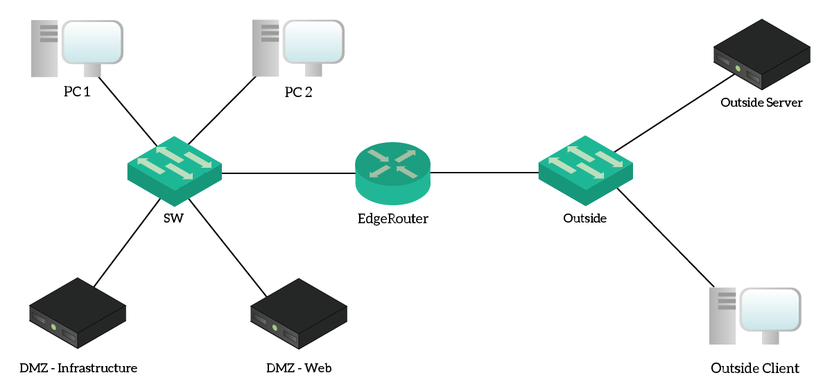 The topology for this lab, at the physical layer (cabling).
The Outside network tries to emulate the Internet, even if it uses a private addressing range. From a security point of view, everything on the Outside network is untrusted. Our goal, here, is to implement stateless security using Access Lists on the . As a result, this router is the only device that we will configure. Instead, we can use the other device to test if we are correctly denying or permitting the traffic.
Since we need to work with source and destination addresses, it will be handy to have a reference of the IP addresses in the lab. For that, we created the following table.
| Address(es) | Name | Notes |
|---|---|---|
| – | Client’s subnet (VLAN 10), DHCP-assigned addresses | |
| Physically hosted on , this website should be accessible only from within the company | ||
| Physically hosted on , this website should be accessible from inside and outside as well | ||
| Example website on the Internet () | ||
| – | Example client on the Internet () |
IP Addressing and Names
Note that both and names resides on the internal DNS server. As a result, the client over the Internet can’t solve these names. Instead, you will need to test traffic by using directly the IP addresses.
The Requirements
We all know that our primary goal is to implement stateless security. However, this sounds a little bit too vague, and this is something we don’t want. When talking about security, we need to be extremely specific. If we don’t, our requests may be misunderstood and this will ultimately lead to a wrong configuration. Since we are permitting or denying traffic, a wrong configuration here can disrupt company services and even cause losses in profits.
Considering this, here’s a detailed list of requirements.
- Verify that traffic coming from the clients’ network is from the expected addressing range, or deny it if not
- Ensure that devices in DMZ can send responses if interrogated for web (HTTP and HTTPs)
- Ensure that devices in DMZ can make HTTP, HTTPs and DNS requests to external devices
- Allow traffic coming from outside to enter the network only if it is a response for a request originated from the inside
- Allow ICMP replies to come in
- Ensure that external devices can reach only the public webserver
- Show the “hit count” for denied traffic
If this is your first time dealing with Access Lists, don’t panic! We will explain how to read these requirements and how to translate them into a few beautiful policies.
Настройка интерфейсов
1. Назначение IP-адреса на интерфейс FastEthernet
Для назначения IP-адреса на интерфейс FastEthernet необходимо войти в режим конфигурации интерфейса:
- Откройте командную строку роутера 1941 в Cisco Packet Tracer.
- Введите команду enable для перехода в режим привилегированного доступа.
- Введите команду configure terminal для входа в режим конфигурации.
- Введите команду interface FastEthernet 0/0 для выбора нужного интерфейса.
- Введите команду ip address , где IP-адрес и Маска подсети соответствуют вашей сети.
- Введите команду no shutdown, чтобы включить интерфейс.
- Введите команду exit.
Теперь интерфейс FastEthernet настроен и готов к работе.
2. Назначение IP-адреса на интерфейс Gigabit Ethernet
Для назначения IP-адреса на интерфейс Gigabit Ethernet необходимо выполнить аналогичные действия:
- Введите команду interface GigabitEthernet 0/0 для выбора нужного интерфейса.
- Введите команду ip address , где IP-адрес и Маска подсети соответствуют вашей сети.
- Введите команду no shutdown, чтобы включить интерфейс.
- Введите команду exit.
3. Настройка VLAN
Для настройки VLAN на роутере 1941 необходимо выполнить следующие действия:
- Введите команду configure terminal для входа в режим конфигурации.
- Введите команду vlan , где номер VLAN – это число от 2 до 4094.
- Введите команду name , где имя VLAN – это произвольное название для идентификации VLAN.
- Введите команду exit.
- Назначьте VLAN на интерфейс:
- Введите команду interface FastEthernet 0/0.
- Введите команду switchport mode access.
- Введите команду switchport access vlan .
- Введите команду exit.
- Введите команду exit.
Теперь на роутере 1941 настроена VLAN и назначен интерфейс для работы.
Предварительные условия
Требования
Для данного документа нет особых требований. Обсуждаемые ключевые понятия справедливы для программного обеспечения Cisco IOS Releases 8.3 и выше. Это указано ниже каждой функции в списке доступа.
Используемые компоненты
В данном документе обсуждаются различные типы списков ACL. Некоторые из них существуют с версии Cisco IOS Releases 8.3, а другие были внедрены в более поздних программных версиях. Это указано в обсуждении каждого типа списков.
Данные для документа были получены в специально созданных лабораторных условиях. При написании данного документа использовались только устройства с пустой (стандартной) конфигурацией. В рабочей сети необходимо изучить потенциальное воздействие всех команд.
Lab Requirements
- Cisco Packet Tracer (7.3.0)
- Resources from my GitHub
- Enter the NetworkTutorial Folder (feel free to check out my other projects)
- Enter the Basic Practical folder and download contents
- Make a directory for the project and copy downloaded contents in it
To really benefit from this tutorial, have a general understanding of how essential network protocols work. To be more specific for this lab, I’d recommend being familiar with:
- Vlans
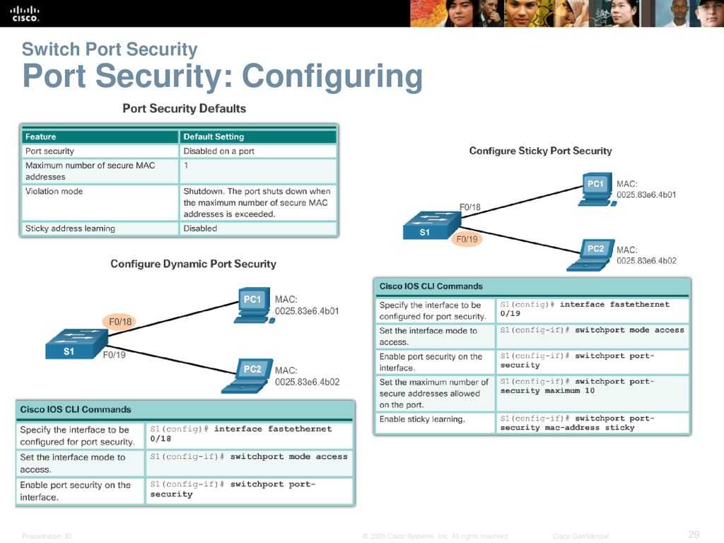
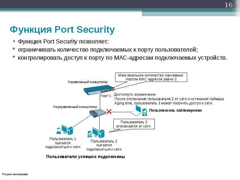
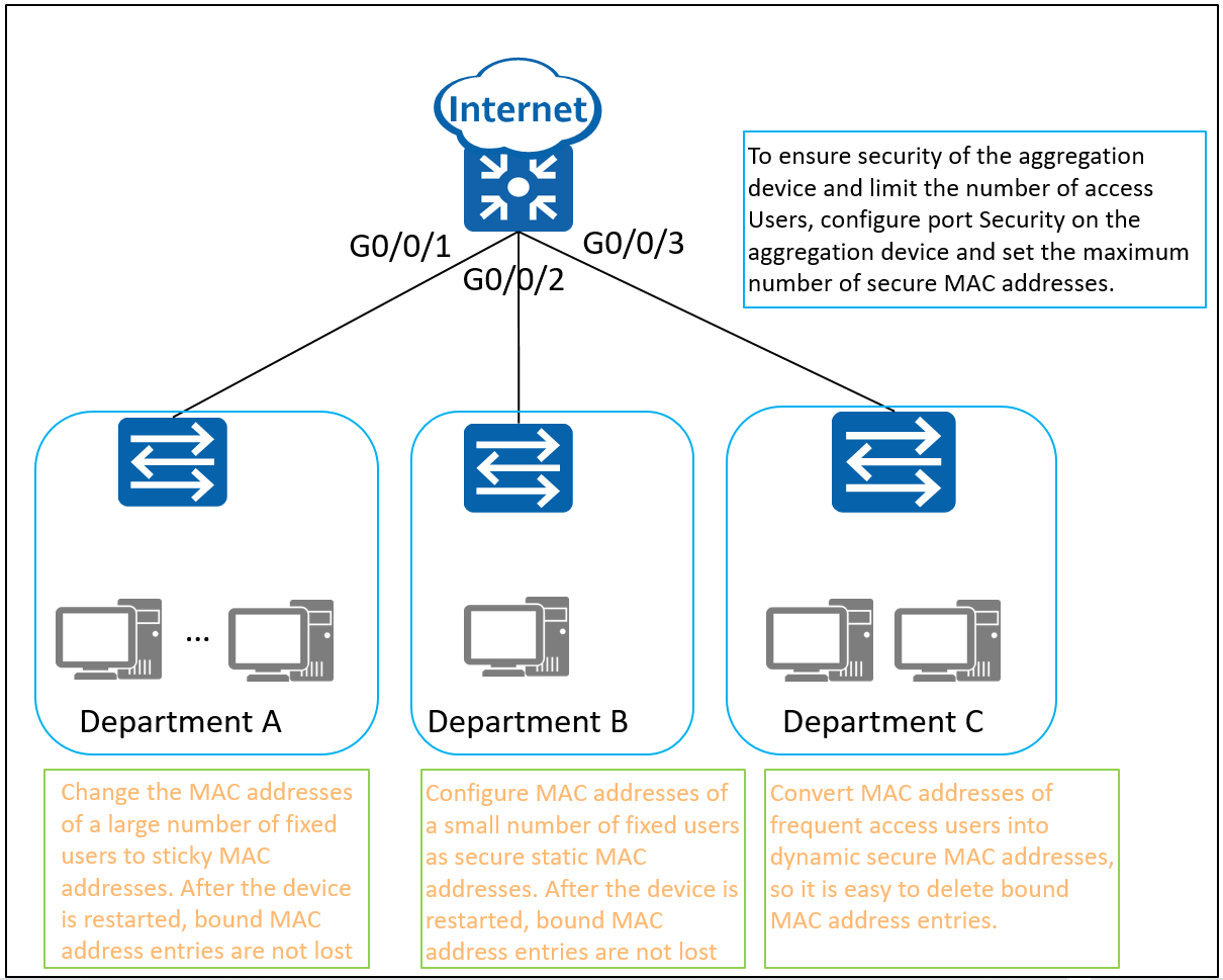
- Switchport Modes and Port Security
- Switch trunking
- Router on a stick
- DHCP
- Access-Lists
- Dynamic Routing (Using EIGRP but at minmum try to learn OSPF as well)
- Static Routing
If some of these terms seem foreign to you please research them first and try to understand their basic purpose in a network. An extensive in-depthknowledge is not required to start configuring and see how these protocols work in action.
If you have trouble understanding them, please reach out in our forums and we will be glad to help!
What are the four 4 steps involved in the troubleshooting of the access control lists?
This how-to walks through a 3 step process to determining if an ACL is to blame for network issues.
- Step 1: Determine Which Interfaces have ACLs.
- Step 2: Determine which ACL Statements Are Effecting Traffic.
- Step 3: Analyze the ACLs to Match Traffic.
- Step 4: Facts to Remeber about ACLs.
How do I configure access control?
Configuring Access Control Lists
- Create a MAC ACL by specifying a name.
- Create an IP ACL by specifying a number.
- Add new rules to the ACL.
- Configure the match criteria for the rules.
- Apply the ACL to one or more interfaces.
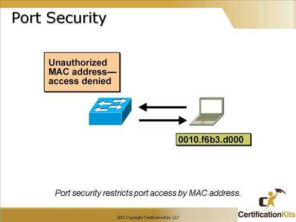
How do access control lists work?
Access control lists (ACLs) perform packet filtering to control the movement of packets through a network. Packet filtering provides security by limiting the access of traffic into a network, restricting user and device access to a network, and preventing traffic from leaving a network.
What is a standard access control list?
Access-list (ACL) is a set of rules defined for controlling the network traffic and reducing network attacks. ACLs are used to filter traffic based on the set of rules defined for the incoming or out going of the network. These are the Access-list which are made using the source IP address only.
Internal server setup
To configure servers in Packet Tracer, simply open the server and click on the services tab.
Take notice that all unused services are turned off.
Before configuring any of these services make sure they are toggled on.
DHCP
Now let’s set up DHCP to dynamically assign IP addresses to end hosts.
The DHCP addressing is determined by the IP table. Let’s add a pool for each vlan.
On the DHCP server:
Click on the services tab, go to DHCP, and fill out the following layout:
When DHCP is configured through a server, the interface vlans should be assigned a helper IP to the DHCP server.
On Internal:
At this point DHCP should be configurable on the end hosts. Simply click on the end hosts, click on config tab and select FastEthernet0 or click on desktop tab and ip configuration; then switch from static to DHCP.
For external it will be configured on the L3 switch instead of a server, which is remarkably similar to a router DHCP config.
On External:
How do I modify a standard access list?
Network administrators modify a standard Access Control List (ACL) by adding lines. Each new entry you add to the Access Control List (ACL) appears at the bottom of the list. Notice deny was added to the top of the list, whereas the additional permit was added to the bottom of the list.
What are the two main types of access control lists?
An access control list (ACL) contains rules that grant or deny access to certain digital environments. There are two types of ACLs: Filesystem ACLs━filter access to files and/or directories. Filesystem ACLs tell operating systems which users can access the system, and what privileges the users are allowed.
How do you configure the standard access control list in packet Tracer?
We will configure the Standard Access-List on router . With this ACL configuration that we have written, we permit PC0 and PC1 to access the server. At the end of ACLs, there is an “Implicit Deny”. These Implicit Deny, prohibits the other IP addresses.
What is the standard access-list?
Access-list (ACL) is a set of rules defined for controlling the network traffic and reducing network attacks. ACLs are used to filter traffic based on the set of rules defined for the incoming or out going of the network. These are the Access-list which are made using the source IP address only.
What is ACL in Cisco packet Tracer?
Access Control Lists (ACL) are used to filter network traffic on Cisco routers. In order to filter network traffic, ACLs control if routed packets have to be forwarded or blocked at the ingress or egress router interface.
What are the four 4 steps involved in the troubleshooting of the access control lists?
This how-to walks through a 3 step process to determining if an ACL is to blame for network issues.
- Step 1: Determine Which Interfaces have ACLs.
- Step 2: Determine which ACL Statements Are Effecting Traffic.
- Step 3: Analyze the ACLs to Match Traffic.
- Step 4: Facts to Remeber about ACLs.
What are the different steps for ACL configuration?
Configuring Access Control Lists
- Create a MAC ACL by specifying a name.
- Create an IP ACL by specifying a number.
- Add new rules to the ACL.
- Configure the match criteria for the rules.
- Apply the ACL to one or more interfaces.
What’s the difference between standard and extended access lists?
A “Standard” ACL allows you to prioritize traffic by the Source IP address. An “Extended” ACL provides greater control over what traffic is prioritized. Extended ACLs can use any or all of the following parameters: Destination IP address.

![[не только студентам] лабораторная работа в packet tracer](https://vvk-yar.ru/wp-content/uploads/6/8/4/68436ba00a12afa54ac8a2f94ee37eb6.jpeg)

Standard ACL Configuration in Cisco Packet Tracer
Standard ACL Configuration in Cisco Packet Tracer,
Cisco Packet Tracer CCNA Labs Adventures!
For more visit : www.ipcisco.com
NAT Configuration Lessons
———————————————————
NAT Overview : https://ipcisco.com/lesson/nat-networ…
Static NAT : https://ipcisco.com/lesson/static-nat…
Dynamic NAT : https://ipcisco.com/lesson/dynamic-na…
PAT : https://ipcisco.com/lesson/pat-config…
Cisco Trainings on IPCisco.com :
————————————————————
CCNA : https://ipcisco.com/course/ccna/
CCNP Route : https://ipcisco.com/course/ccnp-route/
CCNP Switch : https://ipcisco.com/course/ccnp-switch/
CCIE : https://ipcisco.com/course/ccie/
Cisco Hands On : https://ipcisco.com/course/cisco-hand…
PACKET TRACER FILES : https://ipcisco.com/cisco-packet-trac…
CHEAT SHEETS : https://ipcisco.com/protocol-cheat-sh…
QUIZ SECTION : https://ipcisco.com/all-quizes/
#NAT #packettracer #configuration #PAT #DynamicNAT #StaticNAT
Packet Tracer Standard Access List Configuration
In this lesson we will see the Standard Access-List and how to configure Standart Access-List in Packet Tracer.
There are three types Access Lists in common. Thse access list types are :
– Standard Access List
– Extended Access List
– Named Access List
You can DOWNLOAD the Cisco Packet Tracer example with .pkt format at the End of This Lesson.
Standard Access-Lists are the simplest one. With Standard Access-List you can check only the source of the IP packets. On the other hand, with Extended Access-Lists, you can check source, destination, specific port and protocols. Lastly, with Named Access-Lists, you can use names instead of the numbers used in standard and extended ACLs. It do not have too much difference, but it is different with its named style.
In this lesson, we will focus on Standart Access-List Configuration with Cisco Packet Tracer. We will focus on the below topology.
standard acl configuration packet tracer
Here, with our Standard Access-List, we will prohibit PC2 to access the server. But PC0 and PC1 can still access the server.
For our Standard Access-List, we can use the ACL Number 1 to 99. These numbers can be 100 to 199, if you use extended ACLs.
Standard Access-List Configuration
Let’s start to write Standard Access-List. We will configure the Standard Access-List on router .
Router # configure terminal
Router (config)# ip access-list standard 1
Router (config-std-nacl)# permit 10.0.0.2 0.0.0.0
Router (config-std-nacl)# permit 10.0.0.3 0.0.0.0
With this ACL configuration that we have written, we permit PC0 and PC1 to access the server. At the end of ACLs, there is an “Implicit Deny”. These Implicit Deny, prohibits the other IP addresses. Because of the fact that we did not, allow PC2’s IP address, it is autoamtically denied and can not access the server.
Here, there is no need to write but to show how to write deny, I will write the deny command also. As I said before, for this scenario, it is not necesary. But, you can write.
Router (config-std-nacl)# deny 10.0.0.4 0.0.0.0
Router (config-std-nacl)# end
Router # copy run start
Applyin Standard Access-List to the Interface
For more visit www.ipcisco.com
Проверка удаления access list
После выполнения команды для удаления access list в Cisco Packet Tracer, необходимо проверить, что правила фильтрации трафика действительно были удалены. Для этого можно использовать команду .
Команда позволяет просмотреть все access list, настроенные на маршрутизаторе или коммутаторе. Если после удаления access list вывод команды не содержит удаленного списка, значит удаление прошло успешно.
Ниже приведен пример вывода команды до и после удаления access list:
| Before | After |
|---|---|
Extended IP access list MY_ACL 10 permit ip any any |
Extended IP access list MY_ACL |
Как видно из примера, после удаления access list список правил теперь пуст, что говорит о успешном удалении.
Также можно выполнить команду и обратить внимание на отсутствие удаленного access list в выводе команды. Это также будет явным подтверждением удаления